These images shows photographs of the different prototypes which i have made from 1 to 4.
Prototypes were constructed individually based on the design considerations made and the aspects of further improvement form its previous versions.
All prototypes are of full scale.
All prototypes are collapsible.
The description below are only brief observations.
*reference back to previous posts of photographic documentation is advised for recollection.
FIRST PROTOTYPE:
Made as a benchmark to examine structural strength, overall form, functionality, manufacturing possibilities and also user friendliness.
The first use of velcro connections as a unique way of joining the parts together.
The use of exterior flaps to secure the overall form.
The use of cuts instead of folds.
VELCRO & GLUE
–
The exterior flaps are a visual distraction to the continuous outline of the form. (rigid and exposed edges)
The structure lack base support can covering.
More interior structural element could be added to improve the strength.
The width is too wide (based on initial product testing)
SECOND PROTOTYPE:
Made as an improvement step from the previous one.
Overall structure made tapered in the center part to reduce width for better ergonomics. (as discussed after initial product testing)
The use of interior flaps that locks. (top and bottom only)
The elimination of exterior flaps to enhance side profile.
The construction of a full outer shell perimeter covering. (leaves no exposed parts)
VELCRO, GLUE, INTERIOR LOCKING FLAPS
–
Structure looks elegant.
Overall strength improves.
Too many components.
Abit more of pre-manufacturing work to be done.
Construction of the full length shell covering is tedious with the inconsistent widths. (due to the taper)
Internal flaps allow gaps to be seen between the shell an the main body.
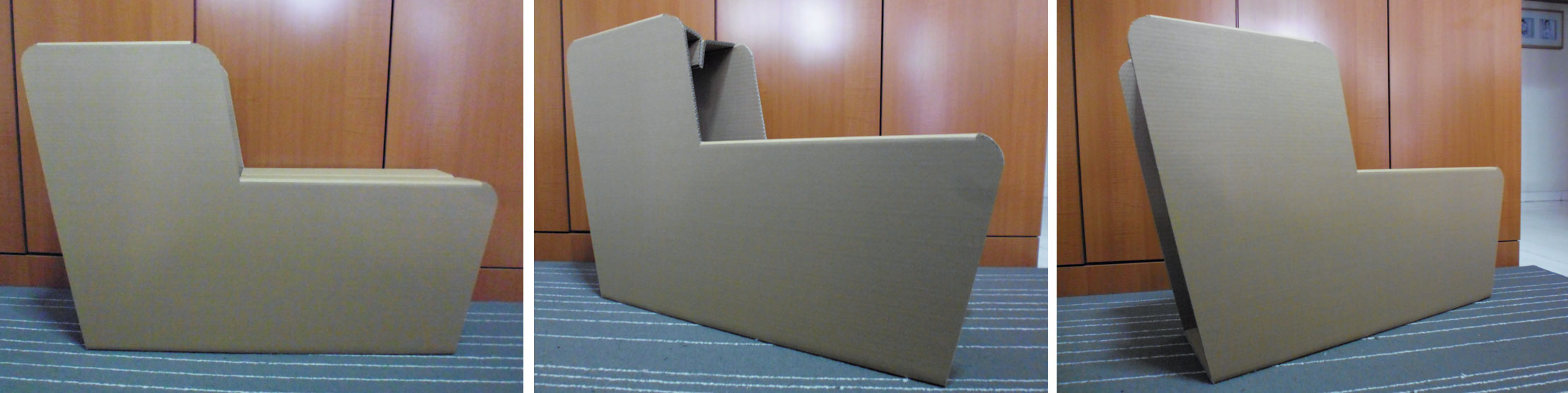
THIRD PROTOTYPE:
Made to improve both strength and finishing.
Design had a size reduction on width. (270mm to 200mm)
No tapering involve.
Main part constructed with layers of cardboard planes to add thickness as surface area for the velcro to fit all over the perimeter
No flaps were involve in this design.
Abit more interior triangular planes were added.
VELCRO, GLUE, BASIC GUIDING SLOT
–
Overall strength improves more.
Still too many components.
Still abit more of pre-manufacturing work to be done but easier than the 2nd one.
Structure looks more balance with the consistent width.
Side profile shows the raw corrugated aspect of cardboard.
FORTH PROTOTYPE:
Made as an alternative method to the 3rd prototype.
The elimination of velcro connection.
Main structure made of several cut planes glued together to give strength and thickness as well as space for the
interlocking flaps to go through.
GLUE, BASIC GUIDING SLOT, INTERIOR LOCKING FLAPS
–
Strength similar to 3rd one.
Raw corrugated aspect of cardboard could only be seen from the top and bottom side faces.
A much more cleaner design.
These are the Sketches of the different ideas of manufacturing for Prototypes 1 to 4.
These are the visual comparisons of Prototype 1 and 3 when the textiles are involved with the design.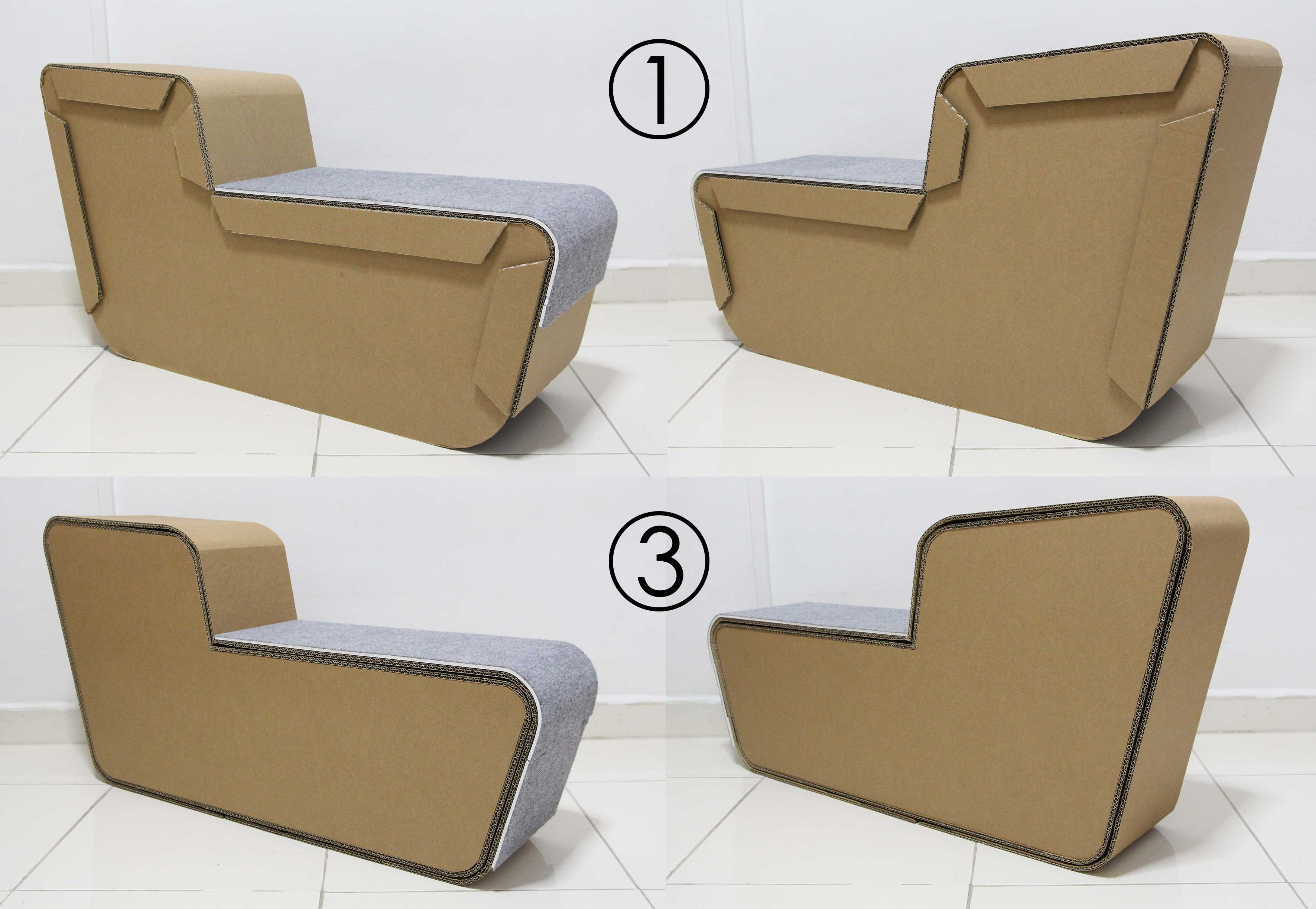 From the results and the experimentation that i have done, it is possible that i might not go on with this design but instead I will similar, better design with a combinations of all the aspects of design and manufacturing listed above.
“Building blocks, Tetris, Easy shapes, Pre school kids (growth development stages)
Parent and child bonding/interaction, Using of mix materials (fabric of textiles to add character to design)”
Characteristics of collapsibility, Stackable, Light-weight Eco, flat packed, DIY, user friendly etc. as discussed will stay in the next design refinements.
 In conclusion, I will still go with the straight edge design. This is because,
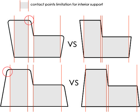
![s [Converted]](../../../../wp-content/uploads/sites/138/2016/02/s-Converted.jpg)